welcome to Henan Pingyuan Mining Machinery Co., Ltd.
- All
- Product Name
- Product Keyword
- Product Model
- Product Summary
- Product Description
- Multi Field Search


Views: 0 Author: Site Editor Publish Time: 2026-09-08 Origin: Site
Struggling to move bulk materials vertically without wasting valuable floor space? Traditional inclined conveyors demand a massive footprint, often forcing plant managers into frustrating layout compromises. As industrial real estate costs continue to soar globally, facility design is undergoing a major transformation. Recent industry analyses indicate a sharp 15% annual increase in demand for high-density, automated plant layouts. Furthermore, with regulatory bodies enforcing stricter environmental and combustible dust standards, maximizing vertical space through fully enclosed transport is no longer just an operational option—it is a strict compliance necessity.
In this comprehensive engineering guide, we will break down exactly how these vertical lifting systems function, analyze the core mechanical components, and provide actionable criteria to specify the right equipment for your facility's unique process demands.
Mechanical Efficiency: These robust conveying systems are specifically engineered to transport bulk materials at a strict 90-degree angle, utilizing a series of attached buckets on a rotating traction mechanism.
Four-Step Mechanism: The operational cycle follows a highly predictable sequence: Loading at the boot, Lifting through the trunk, Discharging at the head, and Returning empty.
Design Variations: Centrifugal and Continuous discharge are the two primary structural designs. Each is meticulously engineered to accommodate specific bulk densities, material fragilities, and optimal belt speeds.
Comparative Advantage: When evaluated against alternatives like vertical screw conveyors, bucket systems provide vastly superior height reach (often exceeding 50 meters), significantly higher throughput capacities, and much gentler handling of friable goods.
Procurement Strategy: Specifying the correct system requires rigorous analysis of material bulk density, required capacity (TPH), and operating environment temperatures to ensure long-term reliability.
To optimize industrial plant layouts, engineers must permanently solve the persistent problem of vertical material transport. A bucket elevator is a specialized, highly efficient piece of bulk material handling equipment designed to lift flowable aggregates and powders straight up. Structurally, it consists of an endless traction mechanism—either a heavy-duty polymer belt (like EP or steel cord) or a rugged metal chain. A series of precisely shaped buckets are securely fastened to this medium. This entire internal mechanism is enclosed within a rigid, dust-tight vertical metal casing and driven by a motorized pulley or sprocket system situated at the apex.
Within complex manufacturing facilities, this equipment functions as the primary "vertical artery." While flat or inclined belt conveyors excel at horizontal transport, achieving significant elevation changes with them requires hundreds of feet of horizontal clearance. Vertical lifters completely eliminate this structural inefficiency. They move dry, granular, or sluggish materials vertically, ensuring continuous flow between processing phases without bottlenecking downstream production.
Due to their scalable capacity, these machines are standardized across multiple heavy sectors. Grain silos and feed mills rely on them to handle corn and wheat without crushing delicate seeds. The mining sector considers them essential for elevating heavy, abrasive loads like crushed ores. Meanwhile, the chemical and fertilizer industries utilize highly corrosion-resistant configurations to transport demanding materials like ammonium sulphate.
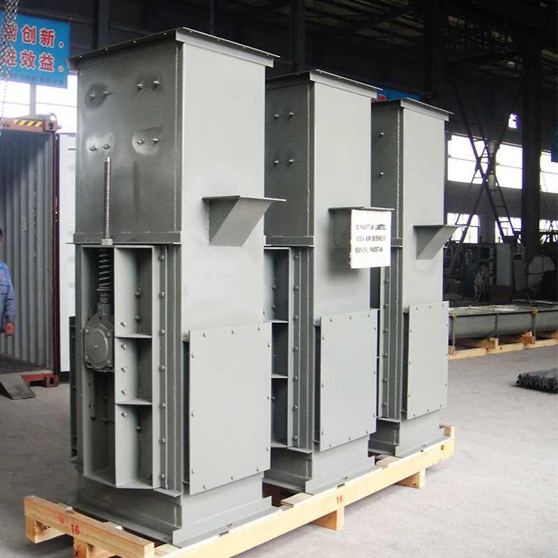
Despite their towering size and massive throughput capabilities, the fundamental operational mechanics of these machines are straightforward. The system operates on a continuous loop, functioning through four distinct, synchronized phases.
Phase 1: The Loading (Feeding) Process
The operation commences at the bottom of the machine, colloquially known as the "boot" section. Picture this area as the staging ground. Bulk material is introduced into the system via an inlet chute. Depending on the engineering design, the material is either scooped up directly from the bottom of the boot casing by the rapidly moving buckets, or it is fed directly into the buckets from a controlled chute. The direct-feed method is highly preferred for fragile or abrasive materials to prevent unnecessary particle degradation and bucket wear.
Phase 2: The Vertical Lifting Phase
Once loaded, the continuous traction mechanism pulls the buckets upward through the vertical housing (the trunk). The drive motor, located at the top head section, provides the necessary torque to hoist the loaded vessels at a steady, engineered speed—typically ranging from 0.5 to 2.5 meters per second. During this journey, the sealed casing ensures the material remains strictly contained. This protects the product from environmental moisture while simultaneously shielding the facility floor from hazardous dust emissions.
Phase 3: The Discharge Phase
The lifting phase concludes when the buckets reach the "head" section. As the buckets pass over the head pulley or drive sprocket, the sudden directional change causes the material to exit. The exact trajectory depends entirely on the elevator's speed and bucket profile. The payload can be aggressively thrown out by centrifugal force into a designated discharge chute, or gently poured over the back of the preceding bucket in slower configurations.
Phase 4: The Return Phase
After successful discharge, the empty buckets continue their rotation over the head pulley. They travel back down the opposite side of the vertical casing. This downward journey returns the vessels to the boot section, completing the loop and positioning them for instant reloading. Tensioning devices in the boot ensure the belt or chain remains taut during this cycle.
Understanding the anatomy of this equipment is crucial for facility managers and procurement engineers. Every individual component must be specified to match the exact physical properties of the material being handled. Off-the-shelf solutions rarely survive in harsh industrial environments.
The Buckets (Shapes and Materials)
Buckets act as the primary vessels of transport. Their geometry directly dictates loading and discharging efficiency. Deep buckets are deployed for dry, free-flowing materials, while shallow profiles are selected for sluggish or sticky substances. Material selection is equally critical. For instance, standard applications might use high-density polyethylene (HDPE) or Q235 carbon steel. However, highly corrosive environments demand 304 or 316L stainless steel to prevent rapid degradation.
The Drive System: Belt vs. Chain
The traction medium is arguably the most critical engineering choice. Belt-driven systems (utilizing EP/NN fabric or steel cords) are capable of higher speeds and are ideal for light-to-medium, free-flowing materials. They offer quieter operation and higher throughput. In contrast, chain-driven elevators (using forged link or plate chains) operate at slower speeds but are virtually immune to tearing. They are the default choice for heavy, highly abrasive, or high-temperature materials exceeding 150°C.
Head and Boot Assemblies
The head section houses the drive pulley, directly coupled to the motor and gearbox. Conversely, the boot section houses the idler pulley and the tensioning mechanism. To maintain operational stability, engineers typically integrate a gravity or screw take-up frame in the boot. This maintains the correct tautness of the traction medium, preventing slippage under heavy surge loads.
When engineering a bulk material handling system, recognizing that one size does not fit all is the first step toward operational efficiency. Manufacturers engineer different custom-engineered bucket elevators based on specific discharge requirements and material behaviors.
Centrifugal Discharge Systems
These are the most commonly utilized designs for free-flowing, durable materials like grain, sand, and dry chemicals. Operating at relatively high speeds (typically 1.2 to 2.5 m/s), they rely on kinetic energy. As buckets pass rapidly over the head pulley, centrifugal force physically "throws" the material into the discharge chute. Because of this high-speed trajectory, buckets are spaced at wider intervals to prevent interference.
Continuous Discharge Systems
If your facility processes fragile materials that cannot withstand aggressive throwing, or highly abrasive ores that would prematurely wear out a casing, a continuous system is mechanically superior. Operating at slower, deliberate speeds (0.5 to 1.5 m/s), the buckets are mounted continuously with virtually no gaps. As they rotate over the apex, material gently pours out. The back of the preceding bucket acts as a natural discharge chute, minimizing degradation and dust.
During the facility design phase, engineers frequently compare bucket systems to vertical screw conveyors. While both elevate bulk materials, their mechanical principles, energy consumption, and ideal use cases diverge significantly.
The primary advantage of the bucket system lies in vertical reach and operational energy efficiency. Because the load is carried inside individual vessels rather than being forced upward through sheer friction, it requires significantly less horsepower per ton of lifted material. Furthermore, material degradation is kept to an absolute minimum.
Engineering Specification | Bucket Elevator | Vertical Screw Conveyor |
|---|---|---|
Maximum Lift Height | Excellent (Often exceeding 50+ meters) | Limited (Typically under 10 meters) |
Throughput Capacity | Very High (Up to 1000+ TPH) | Low to Medium (Usually under 50 TPH) |
Material Handling | Gentle (Carried in vessels) | Aggressive (Grinding/shearing action) |
Energy Efficiency | High (Low friction lifting) | Low (High friction, requires more HP) |
Ideal Applications | Grains, minerals, fertilizers, aggregates | Sticky sludges, highly restricted spaces |
Ultimately, if your facility requires high-capacity throughput, extreme vertical reach, and the preservation of particle integrity, the bucket system is the definitive choice. Conversely, for short lifts handling cohesive sludges, a screw elevator may be more practical.
Integrating a reliable vertical lifting system systematically resolves several pressing operational bottlenecks on the plant floor.
Floor space is an incredibly expensive asset. To move material to a height of 15 meters using a standard inclined belt conveyor, a facility requires massive horizontal clearance to accommodate a 15-degree incline. Vertical elevators bypass this limitation entirely, moving material at a strict 90-degree angle and requiring a footprint of only a few square meters. This maximizes production equipment density.
In addition, product loss through spillage and dust generation severely impacts the bottom line and creates OSHA compliance hazards. The fully enclosed casing of a vertical elevator ensures fugitive dust is contained and easily managed via central dust collection ports, preserving product quality and plant safety.
Investing in heavy bulk material handling equipment requires strict due diligence. Purchasing an off-the-shelf unit without analyzing specific process data inevitably leads to frequent jamming, high maintenance costs, and premature motor failure. Use this actionable criteria for your next procurement:
Analyze Material Characteristics: You must determine the exact bulk density (kg/m³), moisture content, and particle size. For example, specifying chemical industry belt bucket elevators for ammonium sulphate requires anti-corrosive 316L stainless steel and specific EP belts, whereas standard grain handling only requires carbon steel.
Calculate Volumetric Capacity: Capacity is measured in Tons Per Hour (TPH). Always size the elevator for a capacity 15% to 20% higher than your normal processing rate. This "surge factor" allows the machine to handle unexpected upstream feed spikes without stalling the drive motor.
Prioritize Safety and Maintenance: Ensure the design includes strategically placed, gasket-sealed access doors at the boot, head, and intermediate casing sections. If handling combustible organic dusts, ensure the system complies with ATEX or NFPA explosion-proof standards, incorporating blast relief panels and zero-speed alignment sensors.
A vertical lifting system is an indispensable industrial tool, providing highly efficient, space-saving bulk material handling for modern facilities. Choosing the right mechanical components—from the traction belt to the bucket profile and discharge speed—is paramount to maximizing equipment uptime and ROI. Because centrifugal and continuous designs serve completely different engineering purposes, evaluating your specific material characteristics is the most critical step before making a capital purchase.
Whether you are handling fragile agricultural seeds, heavy mining ores, or corrosive chemical fertilizers, specifying the right lifting mechanism dictates your plant's overall efficiency. Ready to optimize your process line and reclaim valuable floor space? Explore the full range of high-performance, custom-engineered solutions at PK Machinery, or contact our engineering experts today for a comprehensive technical consultation tailored to your exact process parameters.
They are highly versatile and can handle a vast spectrum of bulk materials. In agriculture, they seamlessly move free-flowing grains, seeds, and animal feed. In heavy industry, they elevate aggregates, coal, cement, and abrasive ores. They are also widely utilized in the chemical sector for sluggish powders and fertilizers. The key to successful handling lies in selecting the correct bucket shape, casing material, and belt speed.
While the exact maximum height depends heavily on material bulk density and the drive system, these systems are highly capable of extreme vertical lifts. Standard industrial configurations easily reach heights of 30 to 50 meters. For specialized heavy-duty mining or cement applications utilizing reinforced steel cord belts or heavy-duty chains, they can be engineered to exceed 70 meters in a single vertical drop.
Preventing jams requires a combination of proper operational practices and integrated safety sensors. First, material must be fed into the boot section at a controlled, consistent rate to prevent overfilling. Second, maintaining proper belt or chain tension via the boot take-up is critical to prevent mechanical slippage. Modern systems utilize zero-speed switches and belt-misalignment sensors that automatically shut down the drive motor if the belt slows down, preventing a catastrophic jam.
Because they operate continuously under heavy industrial loads, they require a structured preventative maintenance schedule. Routine maintenance involves checking the tension and tracking of the belt, inspecting bucket hardware (bolts and washers) for wear, lubricating head and boot bearings, and verifying pulley alignment. Well-engineered systems feature large inspection doors, making routine component replacements highly manageable for maintenance teams.
Capacity calculation relies on a specific engineering formula. It is determined by multiplying the water-level volume of a single bucket by the number of buckets per meter, multiplied by the belt speed (meters per second), and finally multiplied by a material fill factor (usually 60% to 85% depending on flowability). This gives the volumetric rate, which is then multiplied by the material's bulk density to determine the final Tons Per Hour (TPH).
The primary difference lies in the traction medium, which dictates the application. Belt elevators utilize rubber, EP fabric, or steel cord belts. They run at higher speeds, operate quietly, and are ideal for light-to-medium, free-flowing, or corrosive materials. Chain elevators utilize forged metal chains and sprockets. They run at slower speeds but offer immense tensile strength, making them the mandatory choice for heavy, highly abrasive materials or extreme high-temperature environments (over 150°C).
